Piclone
A Raspberry Pi Pico acts as the ROM and clock for a real W65C02S CPU on a breadboard: single 3.3 V logic, no EPROM, no oscillator can, no level shifters.



The Pico holds a 32 KB ROM image in SRAM and serves it to the CPU’s address bus in real time, generates the PHI2 clock, and drives RESET. A host PC builds ROM images and talks to the Pico over a framed USB-serial Hardware API to upload ROMs and capture bus cycles for automated testing.
Full documentation (wiring reference, firmware internals, API): piclone.big-iron.dev
Table of Contents
Features
Runs a real W65C02S from a Pico-hosted 32 KB ROM image mapped to
$8000–$FFFF.Generates the PHI2 clock (default 1 kHz, ~1 ms/cycle; optional
phi2_hzonread).Drives RESET (open-drain emulated) and auto-starts clock + ROM + reset on USB connect.
Single 3.3 V logic level: no MOSFETs, level shifters, or oscillator chip.
Framed USB-serial Hardware API (JSON) for scripted bring-up and CI.
Structured JSON bus-cycle capture (
readuntilSTP) for automated tests.Optional JSON bus monitor (NDJSON lines) for breadboard observation.
Host-side ROM builder with 6502-address helpers and a
STPterminator.
Architecture
The CPU sees a single 64 KB address space split by A15, which doubles as the chip-select with no external address decoder:
        flowchart LR
    CPU["W65C02S CPU"]
    Pico["Raspberry Pi Pico 2<br/>(ROM + clock + reset)"]
    RAM["AS6C62256-55PCN SRAM"]
    Host["Host PC<br/>(Romulan)"]

    CPU <-->|"A0-A15 / D0-D7 bus"| Pico
    CPU <-->|"A0-A14 / D0-D7 bus"| RAM
    Pico -->|"PHI2 clock"| CPU
    Pico -->|"RESET (GP27)"| CPU
    Pico -->|"A15 = CE#"| RAM
    Host <-->|"USB-CDC Hardware API"| Pico
Memory map:
$0000 ─┬─────────────────────────┐
        │   RAM (AS6C62256-55PCN) │   A15 = 0  → RAM selected
$7FFF ─┤                         │
$8000 ─┼─────────────────────────┤
        │   ROM (Pico)            │   A15 = 1  → Pico drives the bus
$FFFF ─┴─────────────────────────┘
When A15 = 0 the RAM is selected and the Pico stays Hi-Z; when A15 = 1 the Pico serves
rom_image[addr & 0x7FFF] on read cycles (RWB high) and stays Hi-Z on write cycles so the
CPU owns the data bus. The same wire deselects the RAM, so no inverter or decoder is needed.
Hardware
Part |
Qty |
Notes |
|---|---|---|
Raspberry Pi Pico 2 |
1 |
Acts as ROM + clock source |
W65C02S |
1 |
The CPU |
AS6C62256-55PCN |
1 |
32 KB 3.3 V SRAM |
10 kΩ resistor |
6 |
Pull-ups for 65C02 control inputs |
External 3.3 V supply |
1 |
Powers 65C02 + RAM + pull-ups |
Breadboard + jumper wires |
1 |
Full-size (~830 tie-points) recommended |
Not needed: MOSFETs, oscillator can, bypass caps, level shifters.
Wiring
This is the minimum wiring to reproduce the build. For the full per-chip pin-by-pin maps (40-pin W65C02S, 28-pin AS6C62256-55PCN) and the complete Pico GPIO allocation, see the hardware reference.
Board layout
Component placement on the breadboard, left to right: the 3.3 V supply (top-left), the AS6C62256-55PCN RAM, the W65C02S CPU, and the Raspberry Pi Pico 2. Knowing this order makes the two wiring diagrams below easier to follow.
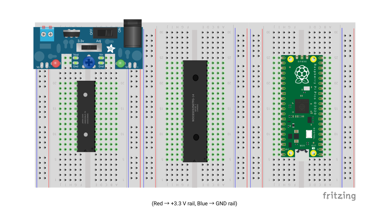
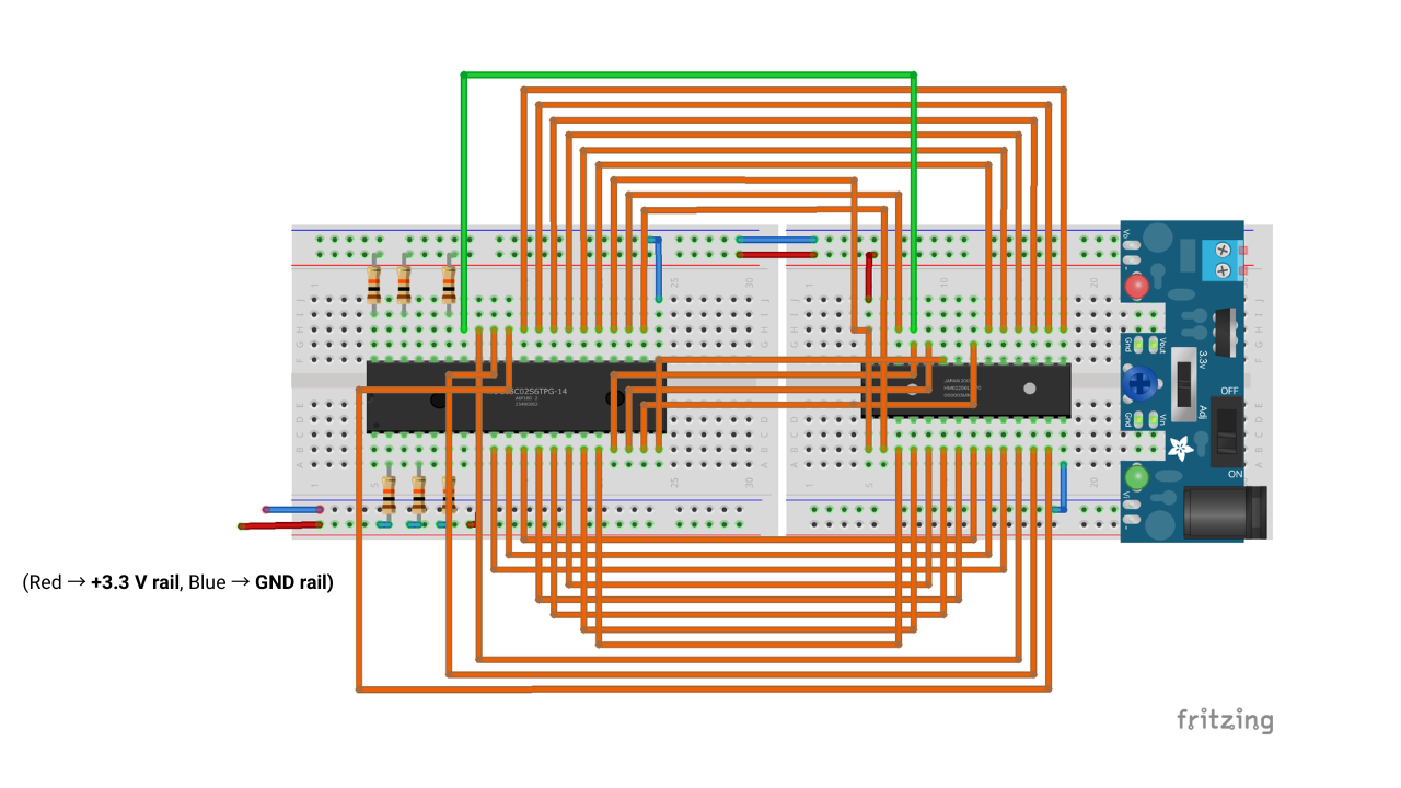
The full wiring is split into two diagrams because routing every net in a single view was unreadable. Both halves share the same 65C02 in the middle; together they form the complete circuit. In both, red = +3.3 V rail and blue = GND rail.
Diagram 1: 65C02 ↔ Pico
The Pico drives the address bus and the ROM data bus, plus RESET and PHI2 (the green wires). Purple wires are the shared A0–A15 / D0–D7 bus; the resistors are the 10 kΩ pull-ups on the 65C02 control inputs.
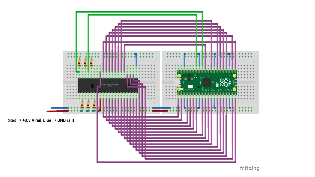
Diagram 2: 65C02 ↔ RAM
The same address and data bus continues from the 65C02 to the AS6C62256-55PCN RAM (orange wires), with RWB → WE# for writes and A15 → CE# for chip-select. The 3.3 V supply module sits on the right.
Point-to-point connections
From |
To |
Purpose |
|---|---|---|
65C02 pin 34 (RWB) |
RAM pin 27 (WE#) |
CPU write-enable to RAM |
Pico pin 32 (GP27) |
65C02 pin 40 (RESB) |
Reset control |
Pico pin 34 (GP28) |
65C02 pin 37 (PHI2) |
Clock at 1 kHz (default) |
(optional) Pico GP23 |
65C02 pin 34 (RWB) |
Not used for protocol |
65C02 pin 34 (RWB) |
Inverter |
RAM pin 22 (OE#) |
Pull-up resistors (6 × 10 kΩ, all to +3.3 V)
Resistor |
Pulls up |
Why |
|---|---|---|
R1 |
65C02 pin 2 (RDY) |
CPU stalls if RDY floats low |
R2 |
65C02 pin 4 (IRQB) |
Inactive (high) when unused |
R3 |
65C02 pin 6 (NMIB) |
Inactive (high) when unused |
R4 |
65C02 pin 36 (BE) |
Bus always enabled |
R5 |
65C02 pin 40 (RESB) |
High when Pico isn’t asserting reset |
R6 |
65C02 pin 38 (SOB) |
Inactive (high) when unused |
Power
Pico: powered from USB only while developing.
Breadboard rail: external 3.3 V → 65C02 VDD (pin 8), RAM VCC (pin 28), RAM OE# (pin 22), and all 6 pull-ups.
Common ground: tie Pico GND, 65C02 VSS (pin 21), RAM VSS (pin 14), and the external supply GND together.
[!WARNING] Do not connect external 3.3 V to Pico VSYS (pin 39) or 3V3 OUT (pin 36) while USB is plugged in. USB back-feeds ~4.5 V on VSYS and fights the breadboard rail, freezing the CPU with a stuck address bus.
Prerequisites
Raspberry Pi Pico SDK + ARM GCC toolchain (set
PICO_SDK_PATH)CMake ≥ 3.13 and
make, firmware targets the Pico 2 (PICO_BOARD=pico2)picotool (optional, for flashing without BOOTSEL)
Installation
Build the Pico firmware (requires PICO_SDK_PATH and arm-none-eabi-gcc):
export PICO_SDK_PATH=~/vsarm/pico-sdk   # your SDK checkout path
cd src
mkdir -p build && cd build
cmake .. -DPICO_BOARD={BOARD_TYPE}
make
The project bundles pico_sdk_import.cmake, so no separate SDK-import step is needed. Output: build/piclone.uf2.
Set up the Romulan host client (a sibling checkout of this repo):
cd ~/Downloads/romulan
uv sync
Pico Board Types
This software supports the Raspberry Pi Pico SoC. Pass the following valid values to the -DPICO_BOARD argument in the cmake command
depending on the board intended for use:
picopico_wpico2pico2_w
Usage
Flash the firmware: see Deployment. On USB connect the Pico auto-starts the clock, ROM emulation, and releases RESET; the built-in demo runs immediately.
Build a ROM image and upload it with Romulan:
cd ~/Downloads/romulan
uv run romulan program.txt --build --upload                 # assemble + upload via Hardware API
uv run romulan hardware upload bin/rom.bin --port /dev/ttyACM0
uv run romulan hardware capture --max-cycles 500 --port /dev/ttyACM0
[!NOTE]
rom_image[]lives in SRAM and is lost on Pico power-cycle, re-upload after each reboot.
Hardware API
The host talks to the Pico over USB-CDC at 115200 baud using a framed protocol. Each transaction is ENQ → STX → ACK → payload → EOT → ACK/NACK; all payloads are JSON with "v":1 (including the chunked, base64-encoded ROM upload). An optional "id" is echoed in responses.
Command |
Request |
Response |
|---|---|---|
|
|
|
|
|
per-phase acks; |
|
|
poll |
|
|
|
|
|
|
|
|
|
|
|
bytes from |
|
|
toggles JSON bus monitor (off by default) |
|
|
full hardware snapshot (clock, reset, ROM, monitor, last bus sample) |
[!IMPORTANT] Don’t open a plain serial monitor on the port while using the Hardware API, and disable
monitorbefore scripted upload/read; unstructured output corrupts framing. Use--read-stp, which disables it automatically.
Full protocol and command reference: Hardware API docs.
Examples
Drive the device from Python using Romulan’s client:
from romulan.hardware_api import HardwareAPI

with HardwareAPI("/dev/ttyACM0") as api:
    print(api.status())

    api.reset(assert_reset=True)                       # hold CPU in reset
    api.upload_rom(open("bin/rom.bin", "rb").read())   # chunked, base64-encoded upload

    capture = api.read_until_stp(max_cycles=500)       # arm capture and release reset
    print(capture.reason, len(capture.cycles))
A captured batch of bus cycles looks like:
{"v":1,"type":"event","event":"cycles","cycles":[{"seq":1,"addr":"8000","data":"18","rw":0}]}
rw is 0 = read, 1 = write. On this build it is inferred from A15 (ROM $8000–$FFFF → read, RAM $0000–$7FFF → write) because Pico 2 GP23 is not a usable header pin for CPU RWB. CPU RWB still drives RAM WE# for real writes. Store cycles should show rw=1; ROM fetches (including STP $DB) show rw=0.
Testing
Automated tests use the JSON bus-cycle stream. End the ROM with a STP (0xDB) instruction so capture stops deterministically:
cd ~/Downloads/romulan
uv run romulan program.txt --build --upload             # demo program ends in STP
uv run romulan hardware capture --until stp --port /dev/ttyACM0
read_until_stp() captures one frame per bus cycle until the CPU fetches STP or max_cycles is reached. Address (and ROM read data) are sampled on the PHI2 rising edge; write data is sampled repeatedly while PHI2 stays high (last sample before the falling edge) so STA bytes stay valid on both Pico W and Pico 2 W. At the default 1 kHz clock, host polling keeps up via a multi-slot firmware queue.
Deployment
Flash src/build/piclone.uf2 to the Pico:
BOOTSEL: hold BOOTSEL, plug in USB, drag the
.uf2onto the mass-storage drive.picotool (device already running firmware):
cd src/build
picotool load -f piclone.uf2
Project Structure
piclone/
├── src/                  # Pico firmware (C, pico-sdk)
│   ├── main.c            # pin setup, PHI2 clock, ROM emulation loop
│   ├── hardware_api.c/.h # v1 JSON command handling over framed serial
│   ├── protocol.c/.h     # ENQ/STX/ACK/EOT/NACK framing
│   ├── json_util.c/.h    # JSON payload helpers (cJSON wrapper)
│   ├── pico_sdk_import.cmake
│   └── third_party/cJSON # bundled JSON parser
├── docs/                 # Documentation website (Sphinx + Doxygen)
└── README.md
[!NOTE] ROM building and host-side control live in the separate Romulan repository, see Host tools.
Documentation Website
The complete documentation (full wiring reference, firmware internals, the Hardware API protocol, and host-tool API) is published at https://big-iron-cde.github.io/piclone/.
Build it locally:
pip install -r docs/requirements.txt
doxygen docs/Doxyfile
sphinx-build docs docs/_build/html
Roadmap
Fail-safe data-bus behavior when the Pico is unpowered (currently back-powered through GPIO protection diodes).
Hot-swap ROM updates via CPU tri-state (BE is permanently held high today).
Add decoupling caps for noise immunity.
PIO + DMA ROM emulation to replace GPIO polling for higher clock speeds.
Contributing
Contributions are welcome. Please open an issue to discuss substantial changes first, then submit a pull request against main. Keep firmware changes in sync with the pin map and the Hardware API documentation.
License
Released under the MIT License.